Amplifier Output Impedance: The Hidden Half of Transducer Control
In textbook audio engineering, the ideal amplifier is treated as a perfect voltage source with an output impedance () of absolute zero. This perspective birthed the ubiquitous industry obsession with the “damping factor.” However, when you couple a real-world amplifier to a complex, frequency-dependent electromagnetic transducer, a zero-ohm source impedance is rarely the whole story.
Instead, is the hidden knob that alters everything from electromagnetic damping to thermal compression and transducer non-linearities. Shifting from a traditional voltage source to a current drive architecture () fundamentally alters this electro-acoustic transduction. By forcing a prescribed current through the load, the amplifier bypasses the localized electrical variations of the voice coil. However, as shifting this impedance boundary demonstrates, this decoupling introduces distinct physical, mechanical, and thermal penalties.
Hysteresis and Flux Distortion Mitigation
In a standard voltage-driven system, the driving current is dictated by Ohm’s law applied to the transducer’s complex impedance:
Because the core material exhibits magnetic hysteresis and non-linear permeability, the instantaneous inductance varies dynamically with both cone displacement and current . This modulates the electrical impedance and heavily distorts the resulting current waveform.
Under current drive, the amplifier dynamically modulates its output voltage to maintain the target current, effectively neutralizing these non-linearities. The driving force becomes strictly proportional to the input signal, bypassing the magnetic distortion loop entirely:
By eliminating the voltage-to-current conversion dependency on the non-linear electromagnetic core, current drive drastically suppresses harmonic distortion induced by hysteresis, particularly in the mid-band frequencies where voice coil inductance dominates.
The Resonance Penalty: Loss of Motional Damping
The most critical drawback of current drive occurs at the transducer’s fundamental mechanical resonance frequency (). When the voice coil moves through the magnetic gap, it generates a back-electromotive force (back-EMF) proportional to velocity:
In a voltage-driven system, the low output impedance () creates a closed loop that allows this back-EMF to generate a counter-current. This counter-current acts as an electromagnetic brake, providing vital electrical damping () to control the mechanical resonance.
Under current drive (), this loop is open. The amplifier’s infinite internal impedance prevents any back-EMF current from flowing. Consequently, the fundamental resonance loses all electrical damping. The system relies solely on weak mechanical damping (), causing a massive spike in acoustic transient ringing around .
The Multitone Blindspot: Measured Evidence via the FE100
Historically, much of the academic literature praised current drive for its mid-band distortion reduction while treating the resonance penalty as a localized, easily managed issue. However, this consensus was largely an artifact of legacy testing methodologies. Standard industry evaluations relied heavily on single-frequency stimuli (such as stepped sine waves), which inherently masked the true complex intermodulation behavior of the transducer under real-world loads.
The real destruction of signal fidelity becomes undeniable when moving from single-tone to multitone excitation, a phenomenon documented extensively in my PhD thesis [1].
When a complex multitone signal spans the spectrum, the transducer’s structural non-linearities (such as motor force factor variation and voice coil inductance ) generate high-order harmonics and intermodulation distortion (IMD) products. Under current drive (), if any of these distortion products fall around the fundamental mechanical resonance frequency (), they hit an undamped resonator. Because the electrical damping is completely removed, the system relies solely on the high mechanical quality factor () of the driver, which acoustic-mechanically amplifies these noise products.
This phenomenon is quantified via direct physical measurement below. The data represents a frequency-domain acceleration spectrum, captured using a miniature accelerometer mounted physically on the cone of a Fostex FE100 transducer. The driver was excited by a multi-frequency stimulus under raw current drive vs. non-linear compensated current drive:
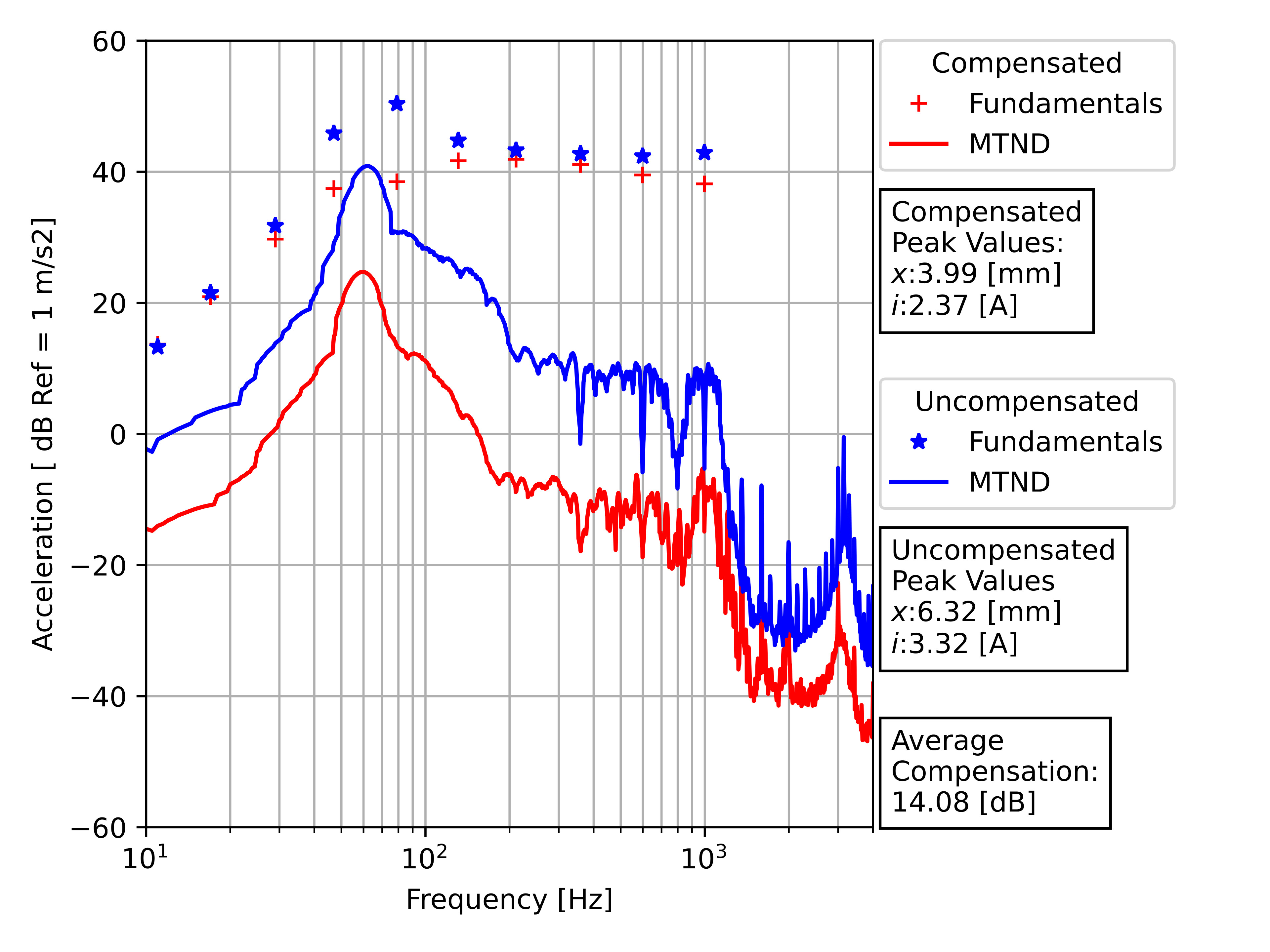
As shown in the uncompensated response (blue curve), the Multitone Noise Distortion (MTND) floor experiences a massive, resonant swelling between and , climbing to within of the fundamental excitation tones. This highlights the catastrophic failure of raw current drive near resonance: the undamped behaves like a mechanical magnifying glass for intermodulation products.
By applying a non-linear compensation algorithm designed to pre-distort the drive signal based on physical state variables—specifically targeting the transducer’s peak displacement and current —the peak excursion is safely reined in from to . The result is an average attenuation of the multitone distortion floor by 14.08 dB across the band (red curve), effectively capturing and restoring mid-band fidelity without sacrificing the intrinsic benefits of the high-impedance drive.
Software vs. Hardware Mitigation: Compensated Current Drive vs. Voltage Driven Shorting Rings
An engineer might counter that current drive is a complex software solution to a problem that can be solved mechanically using copper or aluminum shorting rings (Faraday rings) in the magnet pole piece. To test this hypothesis, a second benchmark was conducted, comparing the non-linear compensated current-driven FE100 against a Fostex FE120 driven by a traditional voltage source (). The FE120 inherently features a physical shorting ring designed to suppress voice coil inductance variations and eddy current distortions.
The comparative acceleration profile, captured via the same cone-mounted accelerometer setup, yields a profound insight into modern transducer design trade-offs:
The spectrum reveals a clear architectural crossover: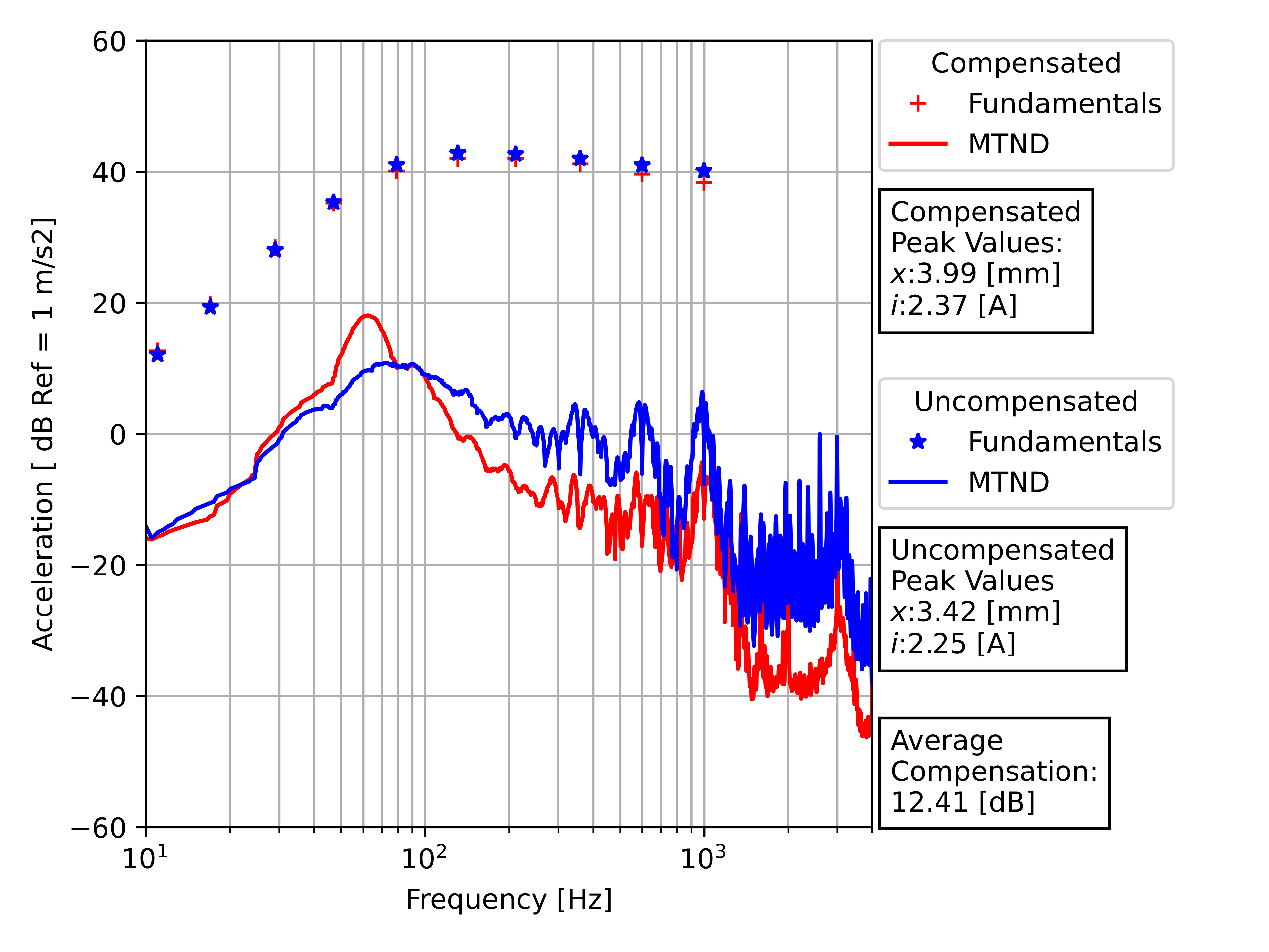
- The Resonance Zone (): The voltage-driven FE120 (blue curve) maintains an inherently lower distortion floor around . This occurs because the hardware-level back-EMF shunting provided by the voltage source’s zero-ohm impedance suppresses motional ringing in a way that algorithmic voltage scaling cannot fully emulate without extreme state-variable sensitivity.
- The Mid-Band and Upper Frequencies ( to ): The compensated current-driven FE100 (red curve) thoroughly outperforms the physical shorting ring, driving the Multitone Noise Distortion (MTND) floor significantly lower. While a shorting ring partially clamps flux modulation, it cannot linearize the system to the degree of an active current-drive loop, which completely decouples the excitation current from the non-linearities of the core material.
Ultimately, the active, non-linear current drive approach secures an average compensation advantage of 9.35 dB across the entire operating band relative to standard voltage driving, proving that DSP-driven transconductance can effectively supplant—and in mid-band scenarios, exceed—traditional electromagnetic hardware optimizations.
Thermal Acceleration and Power Dissipation
Transducers naturally exhibit a significant impedance peak at due to motional impedance, alongside a rising impedance at high frequencies driven by voice coil inductance. Because a current amplifier must guarantee a constant current regardless of the load’s instantaneous impedance , it must scale its output voltage according to:
At frequencies where peaks, the amplifier is forced to deliver substantially higher voltages to maintain the same current. This continuous voltage scaling dramatically increases the real power dissipation () within the voice coil, accelerating thermal compression and shifting the thermal equilibrium of the transducer much faster than a voltage-matched equivalent.
Rail Voltage and Transistor Stress
Driving an inductive load with constant current creates severe challenges for the amplifier’s output stage topology. As frequency increases, the inductive reactance climbs linearly. To maintain a constant current at high frequencies, the amplifier requires exceptionally high power supply rails () simply to overcome the inductive back-EMF:
When the phase angle between the forced current and the high output voltage widens due to this heavily inductive load, the output transistors must endure high voltage drops while simultaneously conducting peak currents. This shifts the operational point dangerously close to the Safe Operating Area (SOA) limits, drastically increasing thermal dissipation within the amplifier’s silicon itself and demanding aggressive heat-sinking solutions.
References and Publications
| Type | Description |
|---|---|
| PhD Dissertation | Munroe, O. “Real Time Loudspeaker Control”, Acoustics [physics.class-ph], Le Mans Université, 2022. NNT: 2022LEMA1022. ⟨tel-03937151⟩ |