Transconductance Power Amplifier
Partners: LAUM (Le Mans University), CNRS.
Why use a Current-Drive Amplifier?
For a compensation algorithm (based on current ) to be effective, it must be applied without interference from the loudspeaker’s complex impedance. A conventional voltage amplifier sees its current modulated by the voice coil inductance and back-electromotive force (back-EMF).
The solution is a transconductance amplifier, where the output current is directly proportional to the input voltage ().
Ideal Topology Comparison
| Amplifier Type | Input | Output | Gain | Output Impedance |
|---|---|---|---|---|
| Voltage | Volts | Volts | V/V | 0 |
| Current | Amperes | Amperes | A/A | |
| Transconductance | Volts | Amperes | A/V |
Design: The Universal “Module”
The innovation here lies in creating a simple, cost-effective module capable of transforming any commercial voltage amplifier (such as the Purifi 1ET400A) into a high-performance transconductance system.
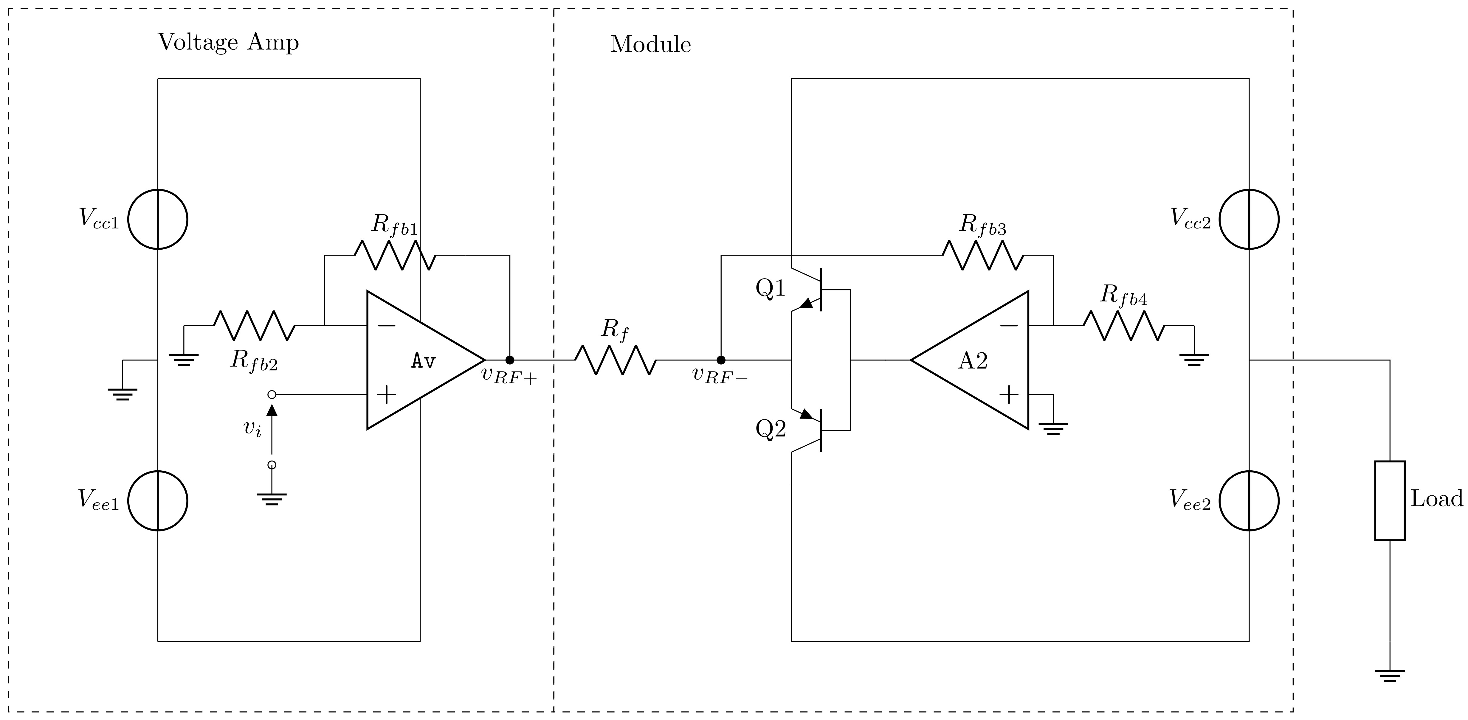
Proposed Topology
The circuit uses an operational amplifier (A2) to maintain the voltage across a sensing resistor () equal to the reference voltage. The load current is then defined by:
Key Advantages:
- Low Cost: Uses modern, readily available components (NE5534, MJL3281/1302).
- Modularity: Adapts to existing power amplifiers.
- Precision: Drastically reduces component count compared to classic topologies (e.g., Mills).
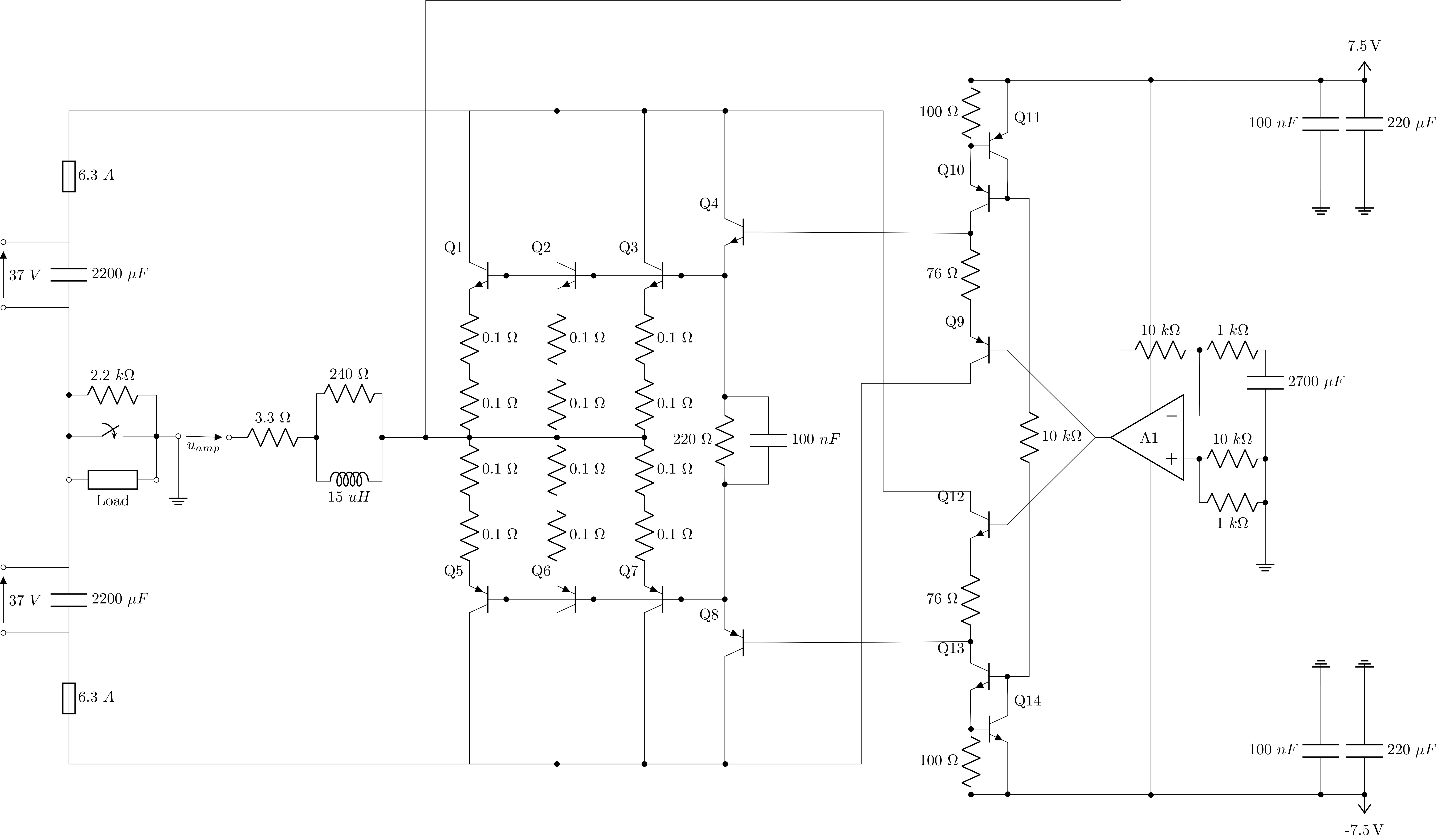
Bill of Materials (BOM)
▶ Click to view critical components list
| Reference | Component | Note |
|---|---|---|
| Q1-Q3 | MJL3281 | Power transistors (NPN), heatsink mounted |
| Q5-Q7 | MJL1302 | Power transistors (PNP), heatsink mounted |
| Q4 | MJE15034 | Driver, heatsink mounted |
| Q8 | MJE15035 | Driver, heatsink mounted |
| Q10, Q11 | BC560 | Small signal |
| Q13, Q14 | BC550 | Small signal |
| Q9 | KSA1381 | Heatsink mounted |
| Q12 | KSC3503 | Heatsink mounted |
| A1 | NE5534 | Op-amp with pF compensation capacitor |
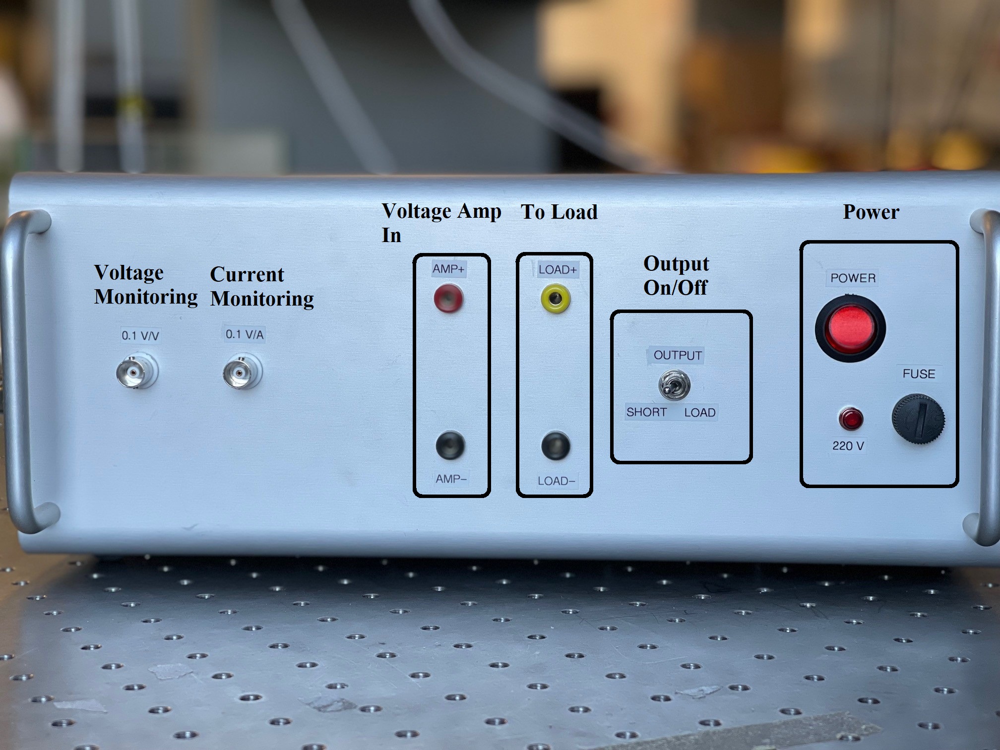
Prototype
A complete prototype was designed, manufactured, and characterized. The tests compare the use of different operational amplifiers (NE5534 vs. TL081) to minimize noise and distortion.
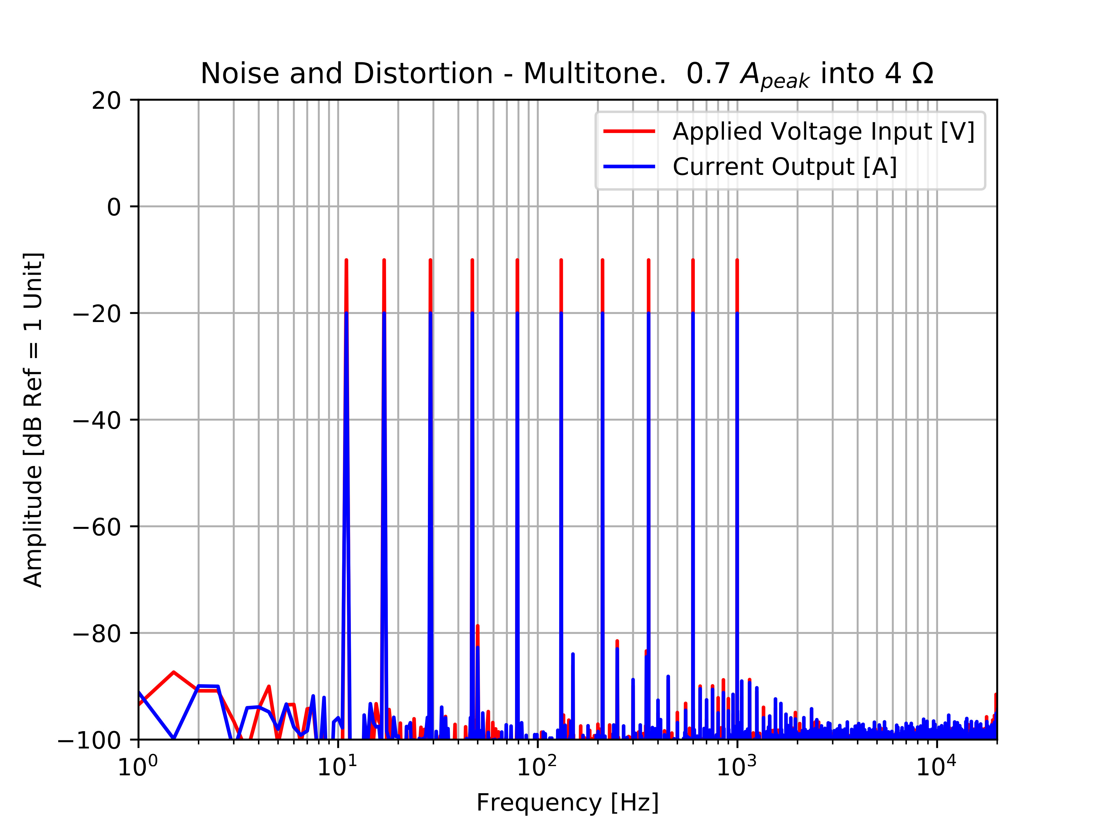
Performance Characterization
The prototype underwent a series of tests (sine waves, multitones, and log-sweeps) using a DT9837C acquisition system to define its operational limits.
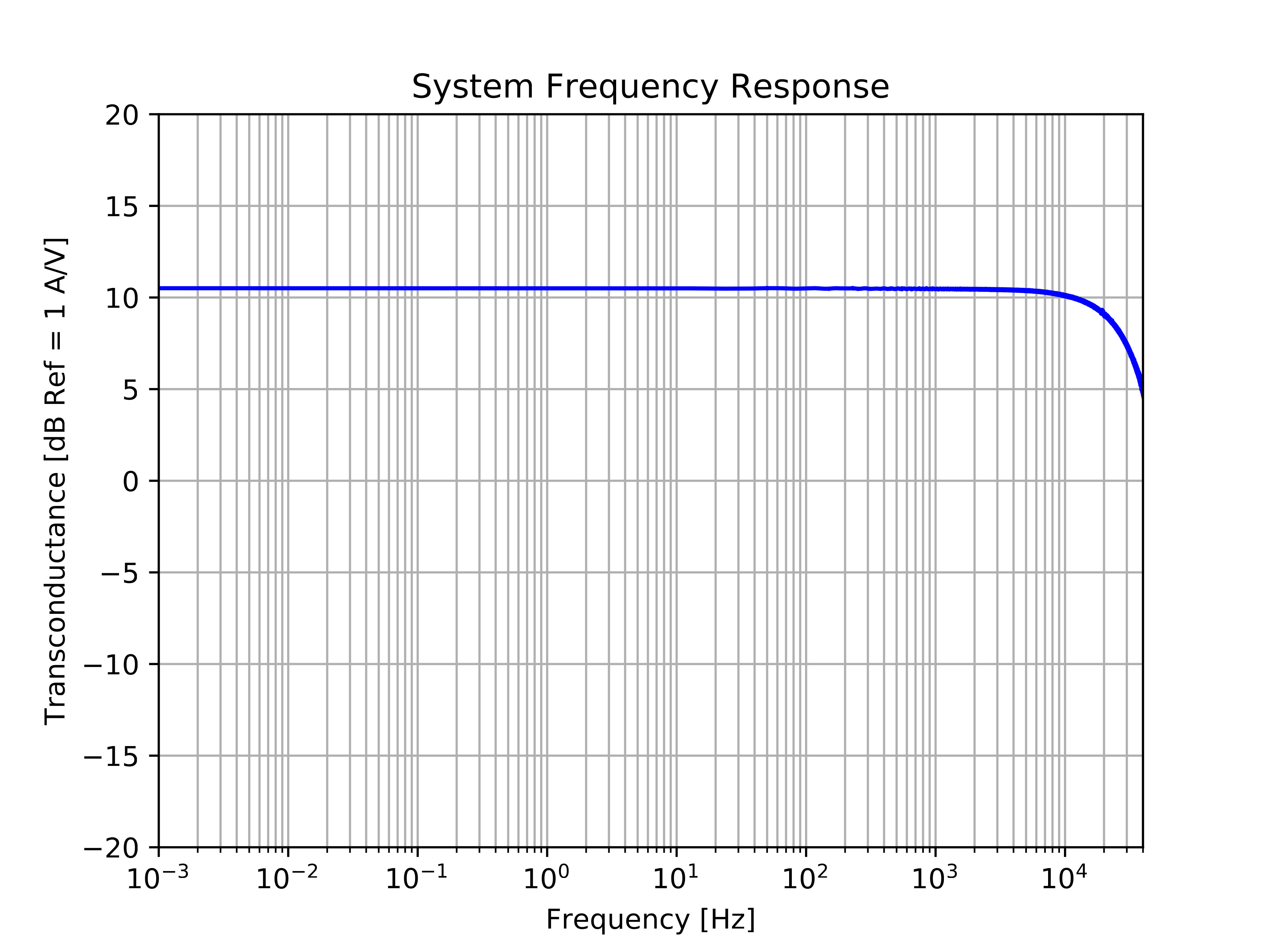
Frequency Response and Noise
The amplifier behaves like a first-order low-pass filter, providing perfect stability over inductive loads.
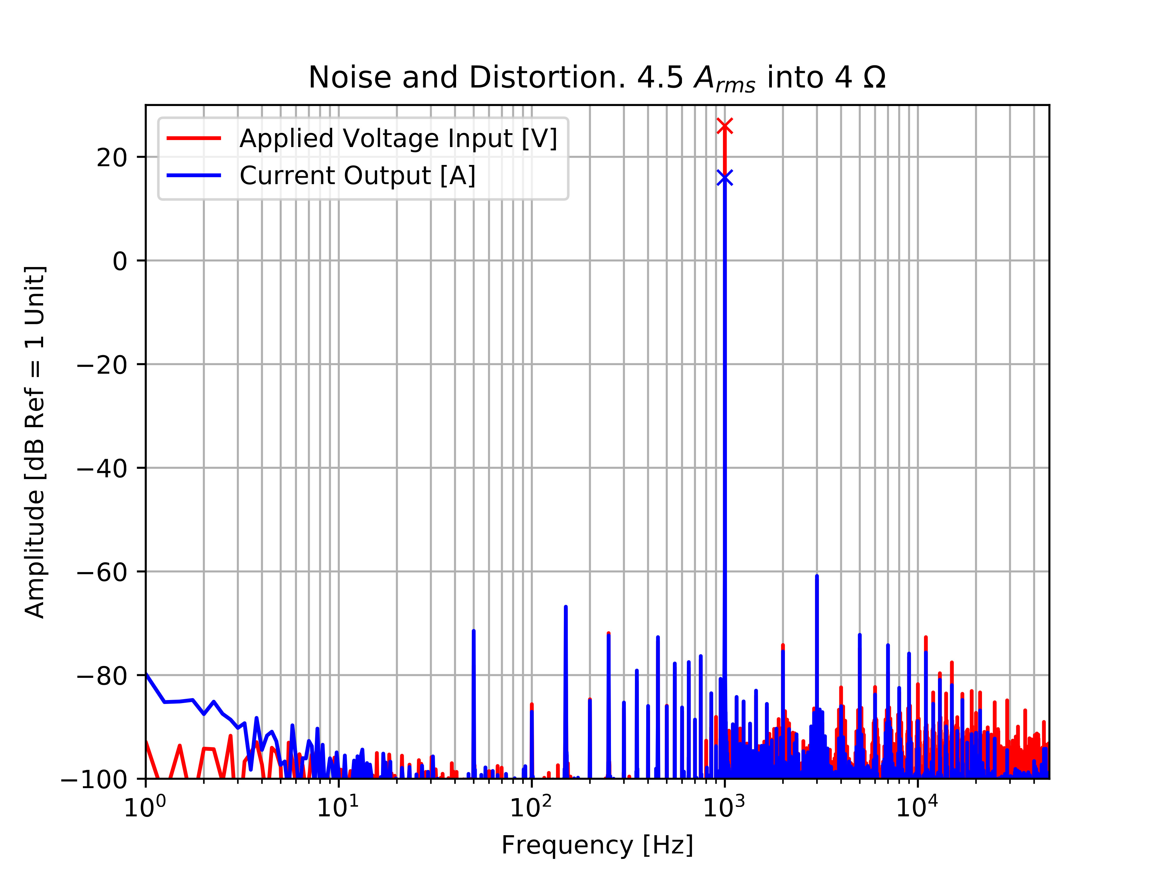
Comparison: PhD Module vs. BAA1000
A key objective was to verify if this “DIY” module could rival expensive industrial solutions like the BAA1000. Noise floor and Total Harmonic Distortion (THD) measurements show nearly identical performance across various power levels.
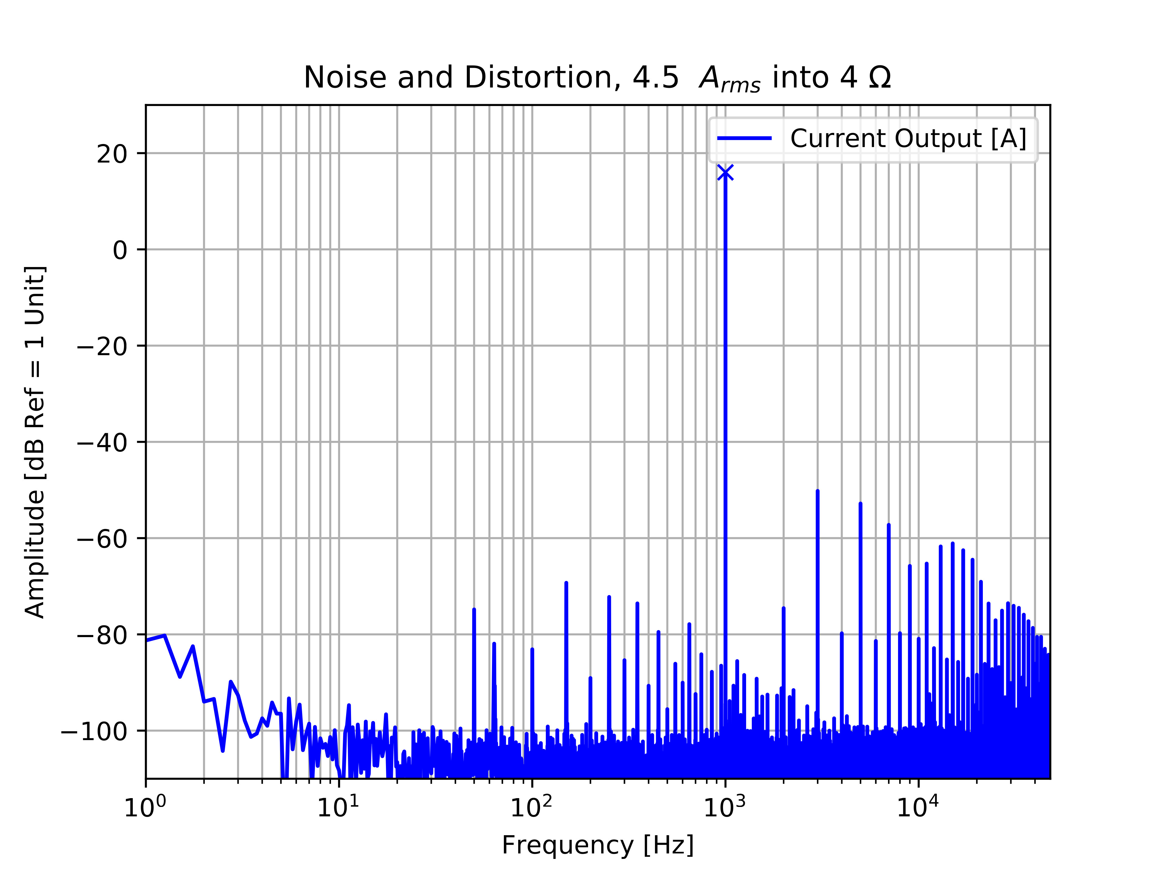
Distortion Spectra (80W into 4Ω)
At high power, the module maintains excellent linearity, limited primarily by the source voltage amplifier used (Purifi 1ET400A).
Component Selection: Op-Amp Impact
A comparative study was conducted between two popular operational amplifiers: the NE5534 and the TL081.
- The NE5534 (with 47 pF compensation) was selected for its superior noise performance and stability at high power.
- The MJL3281/1302 power transistors mounted on heatsinks ensure the thermal robustness required for long-duration testing.
Specifications Summary
The following table summarizes the measured characteristics of the prototype transconductance module. These values demonstrate the system’s ability to drive standard loudspeaker loads with high precision.
| Parameter | Value | Unit | Notes |
|---|---|---|---|
| Output DC Offset | mA | Shorted input | |
| Transconductance | A/V | @ 1 kHz | |
| Input Impedance | @ 1 kHz | ||
| Output Impedance | k | - | |
| Bandwidth | kHz | -3 dB | |
| Input High Pass | - | Hz | DC Coupled |
| Input Low Pass | kHz | -3 dB |
References and Publications
| Type | Description |
|---|---|
| PhD Thesis | Munroe, O. “Real time loudspeaker control”, Chapter: APPENDIX - AMPLIFIER PROTOTYPE, Le Mans University, 2022. |